Kenpilot
-
Posts
211 -
Joined
-
Last visited
Content Type
Profiles
Forums
Events
Everything posted by Kenpilot
-
New to Arduino and DCS Bios. Looking for Help Please
Kenpilot replied to Kenpilot's topic in Home Cockpits
Ok, I put that line in there, now I'm getting this message: Flap_Position_Indicator:12:10: error: #include expects "FILENAME" or <FILENAME> #include "Servo.h ^~~~~~~~ exit status 1 #include expects "FILENAME" or <FILENAME> I forgot a " at the end of the line, but Now I'm getting this message: Flap_Position_Indicator:18:10: error: 'ServoOutput' in namespace 'DcsBios' does not name a type DcsBios::ServoOutput flapPos(0x10a0,9, 544,1472); ^~~~~~~~~~~ exit status 1 'ServoOutput' in namespace 'DcsBios' does not name a type -
New to Arduino and DCS Bios. Looking for Help Please
Kenpilot replied to Kenpilot's topic in Home Cockpits
Ok, I think I've got the idea about the 544 and 2400, but that doesn't help my sketch that won't upload due to the error: " Flap_Position_Indicator:18:10: error: 'ServoOutput' in namespace 'DcsBios' does not name a type DcsBios::ServoOutput flapPos(0x10a0,9, 544, 2400); ^~~~~~~~~~~ exit status 1 'ServoOutput' in namespace 'DcsBios' does not name a type What is wrong with the sketch? Any chance you could write what it's supposed to look like so I can compare them and see what is wrong with mine? All I did was take the Master Caution example sketch, delete what I had copied and pasted from the DCS BIOS control reference for the master caution sketch, and copy and paste the Flap Position Indicator language from the DCS BIOS control reference and it's giving me the above error message when I try to upload it. This is the sketch for the flap position indicator: /* Tell DCS-BIOS to use a serial connection and use interrupt-driven communication. The main program will be interrupted to prioritize processing incoming data. This should work on any Arduino that has an ATMega328 controller (Uno, Pro Mini, many others). */ #define DCSBIOS_IRQ_SERIAL #include "DcsBios.h" /* paste code snippets from the reference documentation here */ void onFlapPosChange(unsigned int newValue) { /* your code here */ } DcsBios::IntegerBuffer flapPosBuffer(0x10a0, 0xffff, 0, onFlapPosChange); DcsBios::ServoOutput flapPos(0x10a0,9, 544, 2400); void setup() { DcsBios::setup(); } void loop() { DcsBios::loop(); } -
New to Arduino and DCS Bios. Looking for Help Please
Kenpilot replied to Kenpilot's topic in Home Cockpits
ok, now that I got the master caution sketch to work, What should the Flap position indicator sketch look like? Do I use the same format as the master caution sketch, just delete the commands for the master caution and copy and paste the commands for the flap position indicator and servo motor from the DCS Bios control reference? Also, in the servo motor command line, it has PIN, 544, 2400 RED. I know what to replace the PIN with, but do I keep the 544 and 2400 or what do I put in their place? Thanks! -
New to Arduino and DCS Bios. Looking for Help Please
Kenpilot replied to Kenpilot's topic in Home Cockpits
When I go in to TOOLS>Port it says "COMM3 Arduino Uno". At the bottom right corner it says Arduino Uno on COM3. In my Device Manager for the PC it says COM3 Arduino Uno. What am I doing wrong? It still gives me the same error message. Disregard. I tried changing USB ports and it worked! I'm not sure which of my USB ports are USB 2.0 or 3.0, but maybe it was one of the 3.0s and it didn't like it? -
New to Arduino and DCS Bios. Looking for Help Please
Kenpilot replied to Kenpilot's topic in Home Cockpits
Copy all, thanks! I'll Check the comm ports. -
New to Arduino and DCS Bios. Looking for Help Please
Kenpilot replied to Kenpilot's topic in Home Cockpits
I made sure DCS BIOS Hub wasn't open and tried to upload the sketch on to the uno and this is the new message I'm getting now: avrdude: ser_open(): can't open device "\\.\COM3": The system cannot find the file specified. -
New to Arduino and DCS Bios. Looking for Help Please
Kenpilot replied to Kenpilot's topic in Home Cockpits
I was. I'll close it out and try again tomorrow. Thanks!! -
New to Arduino and DCS Bios. Looking for Help Please
Kenpilot replied to Kenpilot's topic in Home Cockpits
This is the error message I'm getting when trying to upload the sketch on to the uno. " An error occurred while uploading the sketch avrdude: ser_open(): can't open device "\\.\COM3": Access is denied. And here is the sketch: /* Tell DCS-BIOS to use a serial connection and use interrupt-driven communication. The main program will be interrupted to prioritize processing incoming data. This should work on any Arduino that has an ATMega328 controller (Uno, Pro Mini, many others). */ #define DCSBIOS_IRQ_SERIAL #include "DcsBios.h" /* paste code snippets from the reference documentation here */ DcsBios::LED masterCaution(0x1012, 0x0800, 13); DcsBios::Switch2Pos ufcMasterCaution("UFC_MASTER_CAUTION", 10); void setup() { DcsBios::setup(); } void loop() { DcsBios::loop(); } -
New to Arduino and DCS Bios. Looking for Help Please
Kenpilot replied to Kenpilot's topic in Home Cockpits
Thanks so much guys, I GREATLY appreciate you guys taking the time to help me out. I can get to the DCS BIOS HUB page yes, and that's where I saw the uno is on COMM3 and is connected. I do know how to upload a sketch on to the uno as well. I tried the master caution sketch last night but got an error message and had to call it a night. I'm going to try it again later today and see if I can't figure out what I did wrong. If I still can't get it to work and get another error message I'll post it and see if you guys can help me figure it out. Thanks again!! -
New to Arduino and DCS Bios. Looking for Help Please
Kenpilot replied to Kenpilot's topic in Home Cockpits
Ha, thanks! I have found and read as much as I could from the userguide. Unfortunately I learn from watching, so reading only gets me so far. I'm a visual learner. I'm trying to find videos but I haven't really found any that are useful for a beginner yet. I'll play around with the master caution script and see if I can learn anything from it. Thanks for the heads up on the resistor! -
New to Arduino and DCS Bios. Looking for Help Please
Kenpilot replied to Kenpilot's topic in Home Cockpits
Thanks so much for the response agrasyuk. First of all, awesome simpit!! You do awesome work. I've installed DCS Bios and Arduino IDE, that's about as far as I've gotten. I know the Uno is connected and communicating with dcs bios. I just don't know where to go in Arduino IDE to write the script and how exactly to write the script. Second, I also don't know where to put all the wires in the arduino for the gear handle micro switches, gear indicator light wires (Pos, Neg, and Signal) and the pos/neg of the red LEDs in my gear handle knob, and the flap indicator wires (pos,neg,signal). I'm not connecting anything else from the landing gear lever panel to the arduino uno. Just the Landing gear lever microswitches, the red LEDs that are in the gear handle knob, the gear indicator SAFE lights and the flap position indicator. I found the master caution example from the dcs bios library. Not sure what to do with it though, but if you want to start there, I'm all ears. -
I'm in the midst of building my A10-C simpit and I'm going to use arduino and DCS bios for a few of the panels, but I have zero experience with either one. I have watched a few videos and read through some documentation but I'm pretty lost and I have yet to find anything that takes a newbie like myself from step one to a finished and working panel. If anyone knows of anything like this, PLEASE let me know as I'd love to check it out. I'm a visual learner and typically need to watch someone do it from beginning to end before I really understand and can do it on my own. Or, if you can write a quick how to, I'll take that as well and do my best to work thru it. I have DCS Bios downloaded and installed as well as the Arduino IDE software. The first panel I'm going to use an arduino and DCS Bios with is the Landing gear Panel. I am using an Arduino Uno for the panel. I have the panel completely built and now I need to know how to wire the landing gear level (micro switches, one for gear up and one for gear down) to the arduino, how to wire 2 LEDs in the gear lever knob for when the gear is in transit, the three gear indicator lights for when the gear is down and locked/safe, the flap position indicator(Servo with 3 wires +/-/Signal) and of course all of the wording/coding for the arduino. The anti-skid and landing light toggle switches are just going to be wired to a GP WIZ40 that I already have and installed. Any help or pointing me in the right direction would be greatly appreciated!
-
Ok thanks. Nice looking pit!
-
Did you have to cut the board to size or were you able to find one about the same size as the CDU panel? Yes, I'm planning on adding a display. Thanks for the heads up about the viewing angle.
-
Hey Guys, I'm going to purchase an A10C CDU panel from PC Flights and I was wondering what people use for the circuit board that goes underneath and has all of tactile switches attached? Any suggestions would be greatly appreciated. Thanks!
-
How to set up toggle switches (a tutorial)
Kenpilot replied to Spy Guy's topic in PC Hardware and Related Software
Thanks again LeCuvier!! I figured you might have included the 3 position/function switch .lua but I guess I just didn't know exactly what I was looking for. Got it now. Thank you!! -
How to set up toggle switches (a tutorial)
Kenpilot replied to Spy Guy's topic in PC Hardware and Related Software
Two more questions: 1) How do we get the ALT SCE switch on the Armament HUD control panel of the A10-C to work using a maintained toggle switch? What kind of switch do we use and or what kind of command lines do we use in the .lua? The switch in the game has 3 separate function selections. BARO-DELTA-RADAR. I looked in your default.lua that you posted LeCuvier, but I didn't see anything for this switch, so I'm guessing we keep the .lua the same and use some sort of maintained switch that allows us to select each function? 2) How do we get the HUD MODE DAY/NIGHT switch to work as well? Right now I have an ON-ON switch to choose between the functions, and just wired the DAY "ON" function to one GP-WIZ40 card and assigned it a button, and then wired the NIGHT "ON" function to a different GP-WIZ40 card and assigned it a button. This works, as you can assign a function in the game to two different controller buttons, but you can't assign a function to two different buttons on the same controller if I'm not mistaken? Or can you? Is there an easier way than how I am using this set up with the ON-ON switch and two different cards or is this the only way for this type of switch where there are two different functions for a switch but only one assignment? Thanks!! -
How to set up toggle switches (a tutorial)
Kenpilot replied to Spy Guy's topic in PC Hardware and Related Software
I think the problem with the ON-ON-ON switches that I have, aren't exactly true ON-ON-ON switches that is needed for this game. I think the middle ON position actually combines both the top and bottom ON positions. These switches are most commonly used for guitar pickup selector switches where it "blends" or "mixes" both neck and bridge pickup, so they're both technically ON at the same time. That doesn't work in this game cause then it's trying to tell the game to activate two different functions at the same time. I could be wrong, but from what I've read, researched and checked with an ohm meter, the middle ON position is not a totally separate ON function so to speak. The ON-OFF-ON switch along with LeCuvier's .lua command line works perfectly. Thanks for helping though chickenbone72! -
How to set up toggle switches (a tutorial)
Kenpilot replied to Spy Guy's topic in PC Hardware and Related Software
I tried this and initially my settings/controls page was doing some weird things and then I figured out why... there are two = signs in the command lines and for some reason it was creating havoc in the setting pages. lol But I took one of them out in each line and it works perfectly with the ON/OFF/ON switch!! Thanks again LeCuvier! You're a life saver!! -
How to set up toggle switches (a tutorial)
Kenpilot replied to Spy Guy's topic in PC Hardware and Related Software
Thanks so much LeCuvier!!! That helps a lot! -
How to set up toggle switches (a tutorial)
Kenpilot replied to Spy Guy's topic in PC Hardware and Related Software
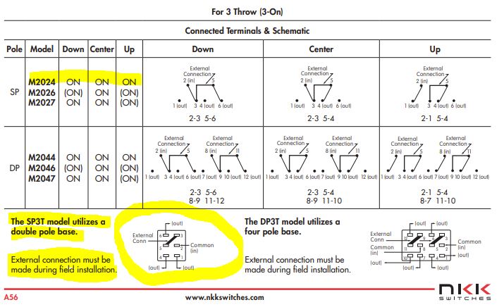
On to my next dilemma. I'm trying to wire a SP3T ON-ON-ON switch (6Poles) for the switches in the A10-C that actually have 3 separate control assignments, one for each position, such as the Lighting Panel switch for Position Lights that have the functions : FLASH-OFF-STEADY. I have been able to wire the switch to get the Top and Bottom ON positions to work, but I can't get the middle OFF position wire correctly. I have tried just about every wire combination that I have found online and nothing works for the game to recognize that middle position being ON. I'm attaching a copy of the data sheet. I have tried to wire it as it's shown, but the game still doesn't recognize the middle ON position when it's selected. I'm using a Groovy Game Gear GP-WIZ40 card. If I can't get this to work, I have seen people use an ON-OFF-ON switch and just edit the .lua files. Anybody have a copy of their default.lua file they can send me or post on here so I can see the correct way to write it for it to work with an ON-OFF-ON switch? Thanks!
-
How to set up toggle switches (a tutorial)
Kenpilot replied to Spy Guy's topic in PC Hardware and Related Software
I got it to work!!!! I thought the new .lua command line only had to go in to the keyboard default.lua. When I did that, it greyed out the control assignment box in the game settings for the APU GEN PWR assignment, and when I hovered over the box, it said "No command available for this device" I then re-read your response over and over again and I noticed you said something about the joystick .lua, which I never looked at or even thought it had anything to do with what I was trying to do because I wasn't trying to re-write anything for the Warthog Throttle or HOTAS joystick. I went in to the joystick file and found the "other" default.lua and entered the new command line in that defualt.lua file as well and that's what did it!! Not only did your command line work that you suggested, but I also tried the : {down = iCommandAPUGeneratorPower, up = iCommandAPUGeneratorPower, name = _('APU generator power'), category = _('Electrical power control panel')}, and it worked as well! Thanks again for your help LeCuvier!!!! Days of frustration finally figured out!! -
How to set up toggle switches (a tutorial)
Kenpilot replied to Spy Guy's topic in PC Hardware and Related Software
Hi LeCuvier, thanks for the response. 1. A10C 2. Groovy Game Gear GP-WIZ40 3. Yes, it does work on the game controller for the ON position only if I leave the .lua files default. I only fly the A10C for right now and I'm not wanting to change anything with the Warthog HOTAS joystick nor the Throttle. I'm creating my own cockpit panels. I'm using maintained ON-OFF or ON-ON toggle switches, whichever will be easier to use for these controls for the A10-C. The controls that only have one button assignment for both ON and OFF functions, such as the Battery Power or APU GEN PWR Switches. I hope this helps. If you need any other information, please let me know. I will try your suggestion here in a little bit when I can get to my simpit. Thank you very much for helping!! -
How to set up toggle switches (a tutorial)
Kenpilot replied to Spy Guy's topic in PC Hardware and Related Software
I tried messing around with the default.lua again and still no luck when using an ON-OFF toggle switch. When I keep the original .lua, it will recognize the ON position of the switch and it works in the sim, except for when I select OFF, obviously nothing happens, so I know the wiring and the switch and the board are fine and communicating, it has to be the coding of the .lua. I have tried what many others have supposedly used and worked, this line: {down = iCommandAPUGeneratorPower, up = iCommandAPUGeneratorPower, name = _('KEN APU generator power'), category = _('Electrical power control panel')}, But when I go to assign the control in the game, the box to assign the control in the control settings is grayed out and it says "No Command available for this device". Any idea why it does that and says that? Guessing again it has something to do with the wording of the wording in the .lua line, but yet, putting in the up = iCommandAPUGeneratorPower, has worked for others. ???? -
How to set up toggle switches (a tutorial)
Kenpilot replied to Spy Guy's topic in PC Hardware and Related Software
Yes, DCS recognizes the Groovy Game Gear Card. My ON-ON switch has 3 terminals. I have a wire connected to the top (#1) termina of the switch and that wire goes to a block connector screw terminal, I then have a wire connected to the middle terminal (#2) of the switch that I connect to the GND terminal of the Groovy Game GP-WIZ40 card. Then I have a wire connected to the bottom terminal (#3) of the switch that is then connected to the same block connector, but under a different screw terminal. I have a jumper that connects all of the screw terminals on the block connector. I then have a wire that is connected under another screw terminal on the block connector that is then connected to the A input of the Groovy Game GP-WIZ40 card. Does that make sense? If not, I'll go take a picture.