

Alburg
-
Posts
46 -
Joined
-
Last visited
Content Type
Profiles
Forums
Events
Posts posted by Alburg
-
-
Not only is HMA Hansolo Mr. A-10 Spareparts of Denmark from today he also is my Dr. RS-485.
So I've been having issues with the RS-485 bus and DCS Bios.
Hans and me where sending emails back and forth until Hans made me the offer of making me a RS-485 shield, but using MAX487 instead, test it and then send it to me.
The best thing all free of charge. So Hans I owe you one :thumbup:
Hooked everything up today, flashed the Master sketch on a MEGA and the SLAVE sketch on a NANO using a USBtiny and then testing the MAsterCaution annunciatior.
As it worked I then tried a MEGA as Master and a MEGA as Slave, as Hans was having issue with this setup.
As this also worked, I modified my already finished sketch of the L/H console on my MEGA to incorporate the slave part of the RS-485.
And it also worked.
So it seems I received three U/S RS-485 shields.
Thanks Hans for your help:thumbup:
-
Boltz I love your panels!
We are making the back panels exactly the same and you are making the front panels the way I am planning to do them when I either buy a CNC router or source someone who has one.
@Hansolo:
Are you talking about the Rivnuts? I don't see any float nuts on the last couple of pictures.
Search for Rivnuts or blind rivet nut on ebay. You'll get them cheap just make sure to buy a halfway decent puller.
Cheers Sven
-
Hansolo Mr. A-10 Spareparts of Denmark :lol:
:thumbup:
-
So I've been busy.
This is Lynxs LH console assembled.
For the start I am going without Lynxs DZUS replica profile (allthough it probably is the onyl correct way to go.)
The Knobs are Deadmans 3d printed ones from Shapeways, except the ones on the Stall Volume panel.
I've already sent my DXF files for the EMERG flight panel and Antenna panel to have them lasered.
For the EMERG Flight panel I actually have sourced all original switches except for the Pitch and Roll Trim switch. I've contacted Thrustmaster for their HOTAS Trim switch and was able to buy one.

-
Good morning everyone,
I've been playing around with DCS Bios and the RS485 bus lately,
but I can't get it to work.
Ian already suggested that I load the sketeches onto the Arduinos using a ISP so I bought a USBTinyISP.
It loads the Master and Slave sketches on the Mega2560s but the communication doesn't work when connected to a MAX485 board.
Then I read that all MAX485 have to share GND, tried that still doesn't work.
Anyone have an idea?
Thanks and cheers
Sven
-
Received a parcel from Denmark today, basically my late Xmas present.
Now even the last neighbour knows that I am a nerdy nerd:megalol:
Looking forward to glue it together.
First impression is top quality from Lynx:thumbup:
-
Sorry wrong thread
-
Hi rocketeer,
you aren't alone!
I have the same issue you have.
-
Hi Ian,
just to let you know I orderd a USBtinyISP still can't get the RS485 working on two MEGAs.
Cheers Sven
-
I am a little surprised that you got onboard LED pin13 on on the master. Are you sure you didn't by mistake load the Slave sketch unto the master? I canøt see if mine are on as I have a prototype shield ontop of mine.
I am pretty sure it's the Master sketch. I marked the Master MEGA this time just to be a 100% certain.
As soon as I connect the USB the LED Pin 13 flashes a few times and then stays on.
Secondly when you power up SOCAT and connect it to the COM's port that the Mega Master is on, AND start DCS; Does you RX/TX led's on the Mega Master flicker to indicate communication from DCS?
Only the TX Led is flashing on the Master.
-
Master I tried TX1 and RX1 now, as I read that the MEGA uses TX0 and RX0 for the USB connections and coms. Pin2 goes to DE and RE of the rS485 Board
Slave
TX0 and RX0 are used on this one
RS485
-
Keep up the good work.
I love it how you get your hands on original stuff!
-
Hi Hans,
thx for your reply.
I've bought two extra MEGAs so I can try the RS485 Bus without having to connect to the already installed MEGA in my LH console.
So this time I tried the folllowing
Master
/*
 Tell DCS-BIOS this is a RS-485 Master.
 You will need to flash this to a Mega 2560.
*/
#define DCSBIOS_RS485_MASTER

/*
 Define where the TX_ENABLE signals are connected.
 You can connect up to three half-duplex RS-485 transceivers.

 Arduino Pin             RS-485 Transceiver Pin
 TXn ------------------- DI (driver input)
 RXn ------------------- RO (Receiver Output)
 UARTn_TXENABLE_PIN ---- /RE, DE (active low receiver enable, driver enable)

 If you have less than three transceivers connected, comment out the corresponding
 #define UARTn_TEXENABLE_PIN lines for receivers that are not present.
*/
#define UART1_TXENABLE_PIN 2

#include "DcsBios.h"

void setup() {
 DcsBios::setup();
}

void loop() {
 DcsBios::loop();
}
SLAVE
/*
 The following #define tells DCS-BIOS that this is a RS-485 slave device.
 It also sets the address of this slave device. The slave address should be
 between 1 and 126 and must be unique among all devices on the same bus.
*/
#define DCSBIOS_RS485_SLAVE 1

/*
 The Arduino pin that is connected to the
 /RE and DE pins on the RS-485 transceiver.
*/
#define TXENABLE_PIN 2

#include "DcsBios.h"

/* paste code snippets from the reference documentation here */
DcsBios::LED masterCaution(0x1012, 0x0800, 13);

void setup() {
 DcsBios::setup();
}

void loop() {
 DcsBios::loop();
}
Without any result.
Is it because maybe the
#define DCSBIOS_IRQ_SERIAL
is missing?
The missing pin you mentioned is the fuel Receiver Lever. I had to do it that way otherwise the function within the game would be mirrored.
Cheers Sven
-
So I've been playing around with the RS485 bus.
I can't get it to work.
So this would be my Master
The Max485 connected to Pin2, TX0 and RX0
/*
 Tell DCS-BIOS this is a RS-485 Master.
 You will need to flash this to a Mega 2560.
*/
#define DCSBIOS_RS485_MASTER

/*
 Define where the TX_ENABLE signals are connected.
 You can connect up to three half-duplex RS-485 transceivers.

 Arduino Pin             RS-485 Transceiver Pin
 TXn ------------------- DI (driver input)
 RXn ------------------- RO (Receiver Output)
 UARTn_TXENABLE_PIN ---- /RE, DE (active low receiver enable, driver enable)

 If you have less than three transceivers connected, comment out the corresponding
 #define UARTn_TEXENABLE_PIN lines for receivers that are not present.
*/
#define UART1_TXENABLE_PIN 2

#include "DcsBios.h"

void setup() {
 DcsBios::setup();
}

void loop() {
 DcsBios::loop();
}
This is my SLAVE the Max485 also connected to Pin2, TX0 and RX0.
/*
 The following #define tells DCS-BIOS that this is a RS-485 slave device.
 It also sets the address of this slave device. The slave address should be
 between 1 and 126 and must be unique among all devices on the same bus.
*/
#define DCSBIOS_RS485_SLAVE 1

/*
 The Arduino pin that is connected to the
 /RE and DE pins on the RS-485 transceiver.
*/
#define TXENABLE_PIN 2

#include "DcsBios.h"

/* paste code snippets from the reference documentation here */
//Fuel Switch Panel
DcsBios::Switch2Pos fscpExtTanksFus("FSCP_EXT_TANKS_FUS", 50);
DcsBios::Switch2Pos fscpExtTanksWing("FSCP_EXT_TANKS_WING", 51);
DcsBios::Switch2Pos fscpTkGate("FSCP_TK_GATE", 49);
DcsBios::Switch2Pos fscpCrossfeed("FSCP_CROSSFEED", 48);
DcsBios::Switch2Pos fscpBoostWingL("FSCP_BOOST_WING_L", 47);
DcsBios::Switch2Pos fscpBoostWingR("FSCP_BOOST_WING_R", 46);
DcsBios::Switch2Pos fscpBoostMainL("FSCP_BOOST_MAIN_L", 40);
DcsBios::Switch2Pos fscpBoostMainR("FSCP_BOOST_MAIN_R", 41);
DcsBios::Switch2Pos fscpAmpl("FSCP_AMPL", 53);
DcsBios::Switch2Pos fscpLineCheck("FSCP_LINE_CHECK", 52);
DcsBios::Switch2Pos fscpFdWingL("FSCP_FD_WING_L", 44);
DcsBios::Switch2Pos fscpFdWingR("FSCP_FD_WING_R", 45);
DcsBios::Switch2Pos fscpFdMainL("FSCP_FD_MAIN_L", 42);
DcsBios::Switch2Pos fscpFdMainR("FSCP_FD_MAIN_R", 43);
const byte fscpRcvrLeverPins[2] = {39,};
DcsBios::SwitchMultiPos fscpRcvrLever("FSCP_RCVR_LEVER", fscpRcvrLeverPins, 2);
DcsBios::Potentiometer alcpRcvrLts("ALCP_RCVR_LTS", A0);

//Stall Panel
DcsBios::Potentiometer stallPeakVol("STALL_PEAK_VOL", A1);
DcsBios::Potentiometer stallVol("STALL_VOL", A2);

//Intercom Panel
DcsBios::Potentiometer intFmVol("INT_FM_VOL", A6);
DcsBios::Potentiometer intIntVol("INT_INT_VOL", A7);
DcsBios::Potentiometer intVol("INT_VOL", A8);
DcsBios::Potentiometer intTcnVol("INT_TCN_VOL", A9);
DcsBios::Potentiometer intIffVol("INT_IFF_VOL", A10);
DcsBios::Potentiometer intVhfVol("INT_VHF_VOL", A11);
DcsBios::Potentiometer intUhfVol("INT_UHF_VOL", A12);
DcsBios::Potentiometer intAimVol("INT_AIM_VOL", A13);
DcsBios::Potentiometer intIlsVol("INT_ILS_VOL", A14);
DcsBios::Potentiometer intHmVol("INT_HM_VOL", A15);
DcsBios::Switch2Pos intAimUnmute("INT_AIM_UNMUTE", 28);
DcsBios::Switch2Pos intFmUnmute("INT_FM_UNMUTE", 33);
DcsBios::Switch2Pos intIffUnmute("INT_IFF_UNMUTE", 24);
DcsBios::Switch2Pos intIlsUnmute("INT_ILS_UNMUTE", 29);
DcsBios::Switch2Pos intIntUnmute("INT_INT_UNMUTE", 31);
DcsBios::Switch2Pos intTcnUnmute("INT_TCN_UNMUTE", 25);
DcsBios::Switch2Pos intUhfUnmute("INT_UHF_UNMUTE", 27);
DcsBios::Switch2Pos intVhfUnmute("INT_VHF_UNMUTE", 30);
DcsBios::Switch2Pos intHm("INT_HM", 35);
DcsBios::Switch2Pos intCall("INT_CALL", 34);
const byte intModePins[5] = {22, 37, 32, 26, 36};
DcsBios::SwitchMultiPos intMode("INT_MODE", intModePins, 5);

//AUX Lights Panel
DcsBios::Switch2Pos alcpFdbaTest("ALCP_FDBA_TEST", 12);
DcsBios::Switch2Pos alcpHarssas("ALCP_HARSSAS", 10);
DcsBios::Switch3Pos alcpNvisLts("ALCP_NVIS_LTS", 11, 13);
DcsBios::Potentiometer alcpRsil("ALCP_RSIL", A3);
DcsBios::Potentiometer alcpWpnsta("ALCP_WPNSTA", A4);
DcsBios::Switch2Pos lampTestBtn("LAMP_TEST_BTN", 9);

//SAS Panel
DcsBios::Switch3Pos saspMonitorTest("SASP_MONITOR_TEST", 20, 19);
DcsBios::Switch2Pos saspPitchSasL("SASP_PITCH_SAS_L", 14);
DcsBios::Switch2Pos saspPitchSasR("SASP_PITCH_SAS_R", 16);
DcsBios::Switch2Pos saspToTrim("SASP_TO_TRIM", 21);
DcsBios::Switch2Pos saspYawSasL("SASP_YAW_SAS_L", 18);
DcsBios::Switch2Pos saspYawSasR("SASP_YAW_SAS_R", 15);
DcsBios::Potentiometer saspYawTrim("SASP_YAW_TRIM", A5);
DcsBios::LED takeOffTrim(0x1026, 0x0400, 17);

void setup() {
 DcsBios::setup();
}

void loop() {
 DcsBios::loop();
}
What am I missing, Í already tried Ians work around with the 470Ohm between GND and A and VCC and B.
Cheers Sven
-
Basically yes.
I'm using a Computer Power supply to run the whole pit. It's actually a quality one from my old gaming PC - Antec CP850.
It has four 12v rails- each can handle 25 amps.
All the PC cables were stripped, grouped into each colour, cut to length and end in terminal blocks.
Ill take some photos and add them here once the wiring has been tidied up- it's a mess at the moment and looking at it now will just confuse everyone!
Sent from my SM-G950F using Tapatalk
Hi RomeoKilo,
I also wanted to go the PC PSU route.
But still guessing around to how many watts the PSU should be able to supply?
At the momement I am thinking 400w should be enough or not?
Thanks and cheers
Sven
-
Hi everyone,
I am currently planing my FM and AM radios.
So for the frequencies I am going 7 segment with a MAX7219.
Now I've been reading that your require capacitors, but the values seem to differ.
So which values are you guys using ?
Thanks and cheers
Sven
-
First of all I wish you guys a happy new year!
So my Arduino MEGA is slowly filling up.
I've been reading about the RS485 BUS.
So I've found out that we require a MEGA to be the MASTER and any other Arduino my be the SLAVE.
I've also found out that it is recommended to use a MAX487 or DS36276 over the MAX485.
The questions I have now
1. Is there any good finished PCD or a plan using a MAX487?
2. Would any other Arduino in the BUS require an external power source?
3. I am currently not using TX (Pin1) and RX (Pin0) on my MEGA would I require any further pins?
4. Do we use half or full duplex?
If I'd install a PSU in my left console how many Watts should be enough?
Thanks and cheers Sven
-
Sorry for the misunderstanding
Cheers
Hans
No worries Hans,
your hint help with a different issue :thumbup:
-
Hi guys,
is it actually possible to invert a switch within DCS Bios or its Arduino programing?
For an example I've wired up the Aerial Refueling Slipway Control Lever switch as normally open.
Having it in normally open makes the lever move to closed in DCS instead of open, when activated.
Yes I know I could just reconnect the switch to be normally closed, but it don'T have enough space for that.
Thanks and cheers
Sven
Thanks to a small hin from Hansolo the problem is solved.
I don't know if it is the correct way but it worked.
const byte fscpRcvrLeverPins[2] = {39,}; DcsBios::SwitchMultiPos fscpRcvrLever("FSCP_RCVR_LEVER", fscpRcvrLeverPins, 2); -
Hi Sven,
Looking good. To answer your question about the MS24659-23D. You can use it as an ON-OFF with DCS-BIOS (simple);
DcsBios::Switch2Pos alcpHarssas("ALCP_HARSSAS", PIN);
Or as an ON-ON with DCS-BIOS (advanced mode);
const byte alcpHarssasPins[2] = {PIN_0, PIN_1};
DcsBios::SwitchMultiPos alcpHarssas("ALCP_HARSSAS", alcpHarssasPins, 2);
Cheers
Hans
Thanks for your reply.
So if I understand you correctly, an advantage of using a ON-ON switch with DCS-Bios, is that DCS-Bios actually knows in which position the switch is in without having to cycle it once you started DCS? With the downside of requiring one more pin on your ARduino?
As an example you left fuel CROSS FEED in the ON position and leave DCS World, then restart the game.
Nothing would normally happen because the game resets the switch to CROSS FEED OFF (in game) put on your panel it is actually still in ON.
But I still think you misunderstood my question.
I just wanted to know if there is a mechanical difference between the MS24523-23 (ON-ON) and MS24523-22 (ON-OFF).
I've had ON-OFF switches where the lever stops would stop at 90° and 135°,
where with an ON-ON the first lever position would be 45° and the second 135°.
Thanks and cheers Sven
-
Hi guys,
is it actually possible to invert a switch within DCS Bios or its Arduino programing?
For an example I've wired up the Aerial Refueling Slipway Control Lever switch as normally open.
Having it in normally open makes the lever move to closed in DCS instead of open, when activated.
Yes I know I could just reconnect the switch to be normally closed, but it don'T have enough space for that.
Thanks and cheers
Sven
-
Just a quick question
Let's for example take a MS24523-23 which is a ON-ON switch.
For us using DCS-BIOS wouldn't also also be possible to use a MS24523-22 which is a OFF-On switch? Or is there a difference in the travel angle between ON-ON and OFF-On?
Thanks and cheers Sven
-
So it's been a while since I've posted something.
For me the racing season ended so now it's time for the sim again.
Unfortunatly fabtools.de stopped business, so I am looking for a new company that lasers aluminium for a reasonable price.
I am still stuck with having no frontplates and I am thinking about have some made without backlight option to start of with.
I am not pleased with my console as it has a "rip" in the way for my Intercom panel to be installed correctly, so I just ordered the newly designed consoles from lynxdk.
Thanks to Deadman one of my panels actually doesn't have a real piece. The knobs for the Stall Warning Volume Panel.
I also managed to source some cheap MS24659-23D toggle switches in Italy, so I guess these are the only correct switches installed in my rig at the moment.
-
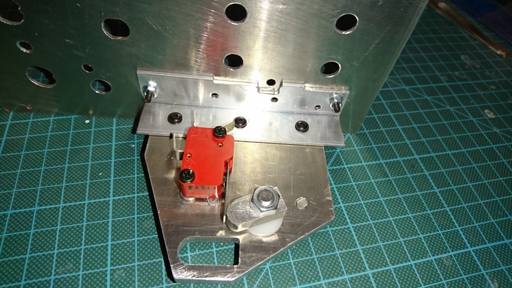
Thanks to the help of Hansolo
I finished version 2.0 of my fuel panel. It basically is a copy of his.
At the moment the L-Profile is screwed to the backplate, but it'll be riveted later.
Cheers Sven


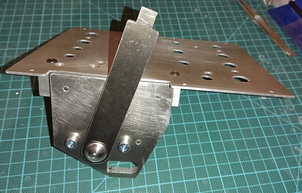
Alburgs A-10 Fuel System Panel
in Home Cockpits
Posted
So something else I've been playing around with is a MAX7219 and some 7 segments (LA-301ML) a friend had left.
I basically would have enough 7 segments to build the two 186 radios and the 164 radio.
The only issue I have with these 7 segments are the pin spacings.
The vertical spacing is 2mm the horizontal 5,3mm.
So I would need to make my own PCB if I want to use them for the final build.
This is just a test to check the output when turning the first frequency select knob.
The dot is just to check if I understood the DP on/off programing.