
rel4y
-
Posts
968 -
Joined
-
Last visited
Content Type
Profiles
Forums
Events
Posts posted by rel4y
-
-
Great news guys, it's done, it's finished, it's aaaliiiive!

Now I can proudly say I have actually finished the force sensing project, after what.. like 3,5 years?! Although in 2021/22 pretty much zero work was done due to family and C19. I had all of the mechanical parts already laying around but the electronics were still very much rudimentary. In early 21 I had made a few for a commercial project, but with a completely different electronics layout as they wanted I2C comms with sigma delta ADCs for a very specific MCU.
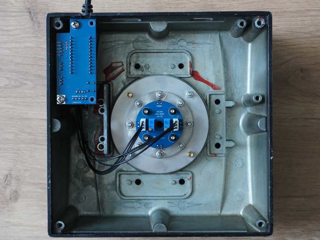
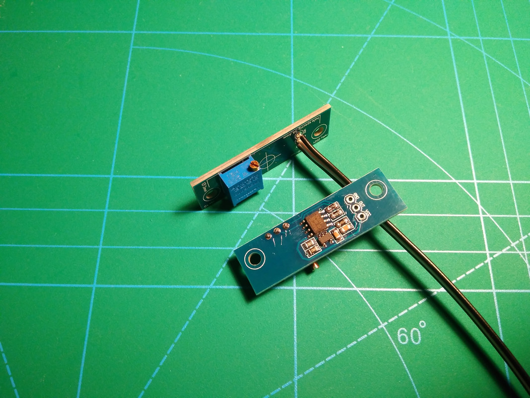
I am super happy with the electronics now. It is already the third tested revision of this PCB layout and I spent a lot of time optimizing filters. The supply filtering as well as output filtering are spot on and noise is several factors lower than on the FCC3. Contributing to a low noise floor is a different type of resistor that I changed to recently, they are about 25x the cost compared to standard 1% resistors but in bulk it's still just penny stuff. In the following picture you can see rev 1.2 and 1.3 in my Cougar prototype setup. The production units will have all standard nuts replaced with locking nuts, but for ease of dis/assembly I chose not to use them. Also you can see wires sticking out on the side, that's just the prototype so I can switch between PCBs and quickly solder them back on.
Second pic shows the FCC controller installed in the Cougar base working in combination with the FCC R4. The joystick button cable for the shift regs is not soldered on, again for ease of swapping out PCBs. However, I did test it separately and it works flawlessly. The FCC controller mounts without any problems to the Cougar base and would be a good replacement for broken Cougar mainboards even if using the standard Cougar gimbal.
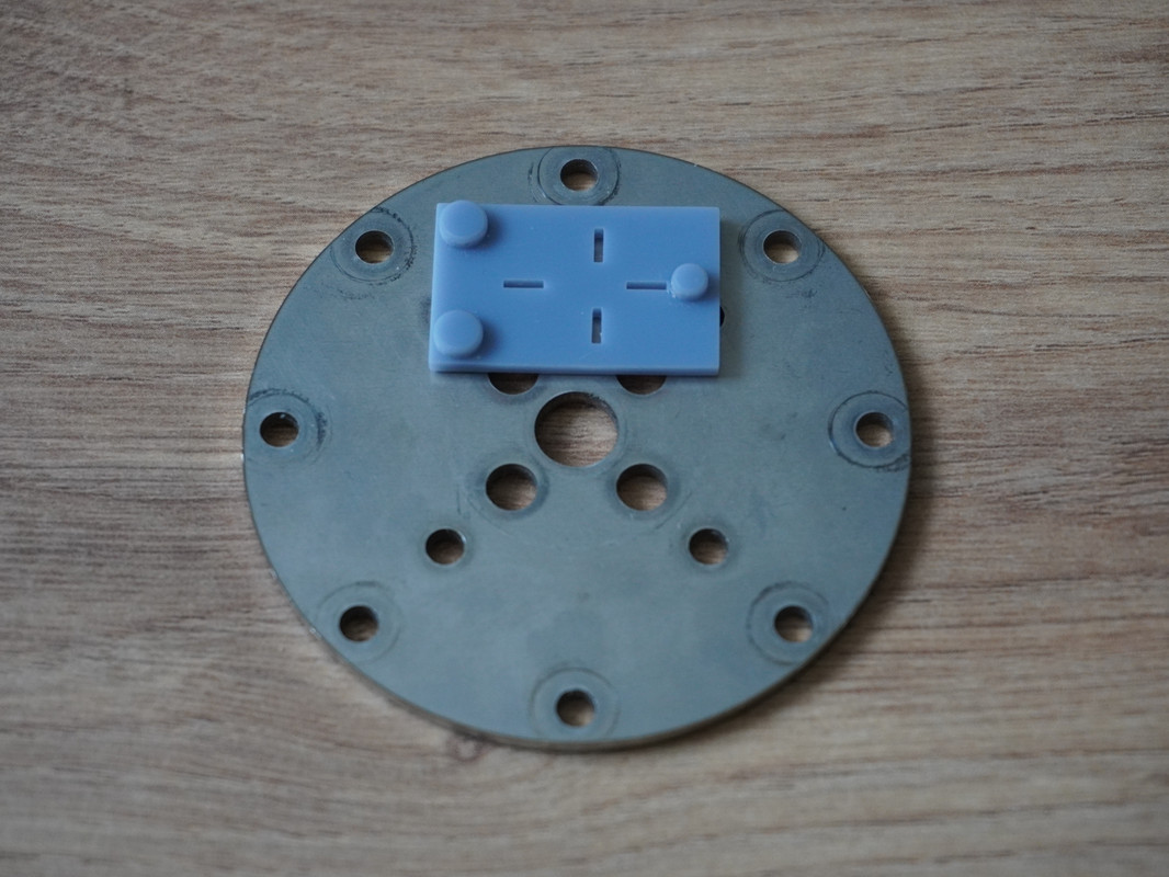
I've also 3D printed a jig for sensor placement, although the slits are too wide on this one and I will reprint it.

The FCC controller is still missing two LEDs for hardware indication of X&Y axis center position, but the ADC filter is now complete. Since I needed new connectors for the Cougar Ministicks which can currently only be sourced from Japan, I ordered some quality filter components together with them. In hindsight that was a pretty bad decision, because the Japanese electronics supplier sent me several packages and for each of them I had to pay a ridiculous amount of import taxes and DHL fees.. Well, s.. happens, at least the filters are working well!

The FCC controller has a reset button to activate the bootloader. That way one can even easily flash MMJoy2 and I've made a preconfigured profile as well. The small 6pin connector is for the Warthog joystick buttons, the larger 5pin for the Cougar. For Warthog installation I'll need 90deg connectors, which are already in the mail.
That's where I made a stupid mistake.. To get the Warthog mounting holes correct I actually took the time to make an accurate CAD model of the Warthog base lower ring (third pic). Next, I mistyped the measured distance by exactly 1mm on the PCB layout editor and now the Warthog mounting hole spacing of the FCC controller is off. I think it still fits, but can only be mounted with one screw... bummer!

Fourth pic shows the comparison to Cougar and Warthog mainboards.
In terms of Software, the FCC controller will be running @uri_ba amazing software as standard option. I will contact him regarding a few minor quirks I found and maybe he will find the time to iron them out!
 First pic shows the FCC controller interface with the optional sensor rotation enabled, as it is in the real aircraft. I moved the stick only vertically and horizontally and the software does the offset. You also have the option of proportional force mapping accurate to the real F-16 analog or digital FLCS. Now the preconfigured sensitivity settings will not be accurate, as my FCC R4 has higher max force limits than the FCC3 (which has ~4-6kgf at max output).
Second picture shows the FCC controller configured with MMJoy2 and no filtering whatsoever, so plain raw signal. On the right side you can see me jitter perpendicular to the input axis at higher forces, as apparently I need to give the gym a visit (and I was simply holding down the Cougar base on the table with my second hand). I noticed even when walking around in the room it picked up the vibrations... pretty crazy.
Flashing MMJoy2 over uribas software can simply be done via the reset button, the other way around is not so straightforward as it turns out. MMJoy2 apparently overwrites the bootloader and I needed to reflash it via my trusty old USBasp (third pic).
QuoteInitial implementation was referred to as “Analog FLCS” as the pressure sensing gains were all hardware driven (pre-amps, resistors etc.), which meant that whatever forces the SSC was initially designed for were there to stay. The Analog FLCS was calibrated so that the full pitch up command (+10G) required 180N (40.46 lbf / 18.35Kgf). Full pitch down command (-4G) on the other hand required 80N (18 lbf / 8.15Kgf), full roll was also 80N.
With block 40/42 the “Digital FLCS” was introduced. Unlike it’s predecessor, the electronics on it were programmable and it was possible to change the gains from the device. According to the Dash1 manual in the block 52+, the current gains are 25lbf (111N / 11.34 Kgf) for full pitch up and full pitch down is 16lbf (71N / 7.25Kgf). While the full roll command is 17lbf (7.7 Kgf / 75.6N).
I actually tried the older style analog SSC forces required on my prototype (a ridiculous 40.46 lbf / 18.35kgf for full pitch up) and it is simply no fun whatsoever. No wonder the pilots complained, I get tendinitis just by thinking about it.. Therefore I decided to go for the modern digital SSC force limits with 25lbs max pitch and that can be digitally turned down to a flightsimmer friendly 13lbs/ 6kgf or even lower if desired.
 Now here is the question to you guys. Would you prefer the real deal digital SSC limits aka 25lbf / 11.34 kgf or the usual 6kg such as FCC3/ FSSB R3. I'd always go for realism, but it definitely still is a workout and you do lose some precision when digitally setting lower force settings.
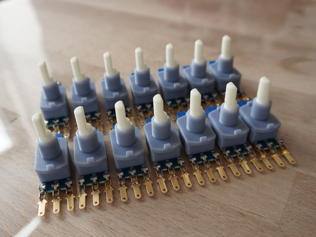
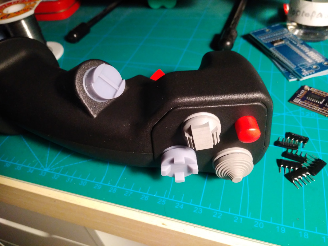
Currently I have enough parts for 20 units. Three of them are already reserved for people who helped me out massively in designing the FCC R4 and will be sold for parts cost. The first unit, aka my prototype will stay with me, so there are 16 units left to be sold in the first batch. For this first batch I will include a set of replica F-16 DMS & CMS hatswitches for the Cougar/ Warthog as a thank you gift (see pictures below). The electronics on the FCC R4 will have a three year warranty included, but that's for legal reasons and honestly if something breaks after these three years I'll likely fix it anyway, as I've done with my older mods. If you manage to break any of the metal parts, then I'd be really surprised.
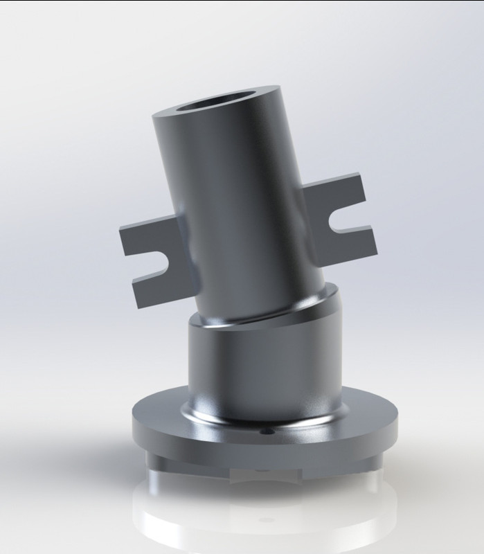
If you legends would help me spread the word and sell these 16 units, then I will have recouped all my R&D costs and even have some funds left over for my next projects. These next projects will include a replica F-16 force transducer Slew for Cougar and Warthog Throttles, based on similar electronics as the FCC R4. Secondly forged carbon fiber F-16 pedals and angled Cougar/ Warthog tailpieces. As you may know the CAD models for these are done, I just need to spend the cash to buy the composite materials and make compression moulds.
On 9/28/2023 at 7:05 AM, sirrah said:This is sooo recognizable

Good to hear from you again!
That FCC R4 is looking good
 . Also good to see that you are making it standalone (I have 2 Cougar bases sitting around, but both PCB's seem dodgy). I know it's still early, but what price tag are you aiming for?
Hey mate, hope you are doing well! Happy to see you are still following my projects after so many years!
Let's talk prices then.
FCC R4 aka simpit version: 299€
optional Cougar/ Warthog mounting plate + hardware: 10€
optional FCC controller: 35€
Shipping: need to research that, but I'm aiming for 10€
Edit: Prices include VAT already.
-
 7
7
-
 2
2
-
-
I've been wanting to post an update for almost two weeks now, but my kids and then of course the whole family had an especially nasty case of the Kindergarten flu. I swear Kindergarten/ preschool is actually some sort of government funded bioweapons factory, every germ that gets out of there is ten times worse than anything you could ever pick up at work...
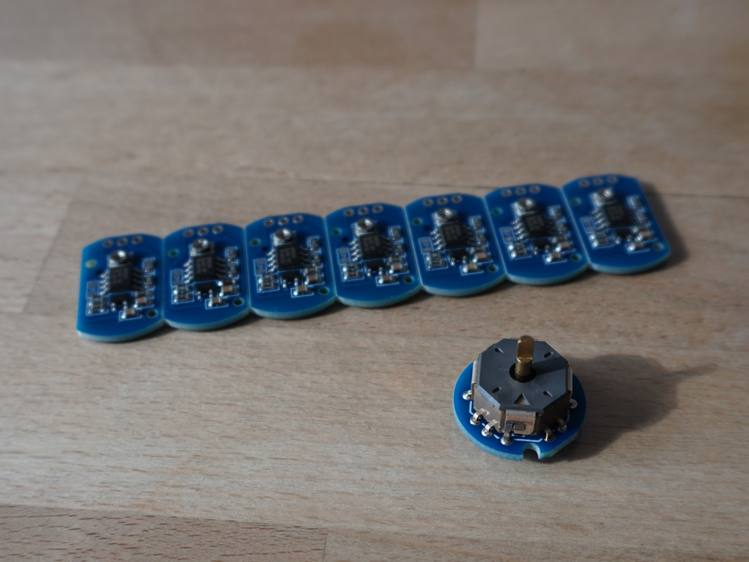
I've made a new batch of CH sensors and have three 12 Bit CH upgrade mainboards left. I think I'll pull the CH mainboards from my portfolio as they are a bit of a hassle to solder and interest has slowly faded over the years. I'll keep the CH sensors though so people can always find spares for their ageing CH devices. Actually I've just tested a new type PCB with an SMD mounted trimpot instead of the large blue trimmers for the CH sensors. Definitely more complicated to calibrate initially, but it results in a significantly smaller sensor.
Third pic also shows the new PCB + ALPS 9-way switch for the replica F-16/ Mason/ OTTO trim hats. I haven't printed the F-16 trim hat & case yet, as I need to adjust a few dimensions from my experience with the replica T4 Mini hatswitches.
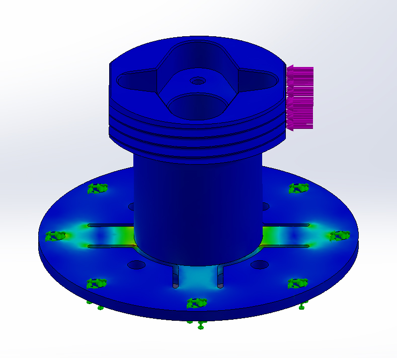
Last time I forgot to mention that I also considered the "classic" force transducer layout for the FCC with cutout tabs (such as used in the FSSB). I ran an FEA stress simulation on this and found no real benefit over the more sleek looking plain plate. Yes, the stress is isolated in the cutout tabs, but other than a minimal reduction in signal amplification there is not much difference. Arguably axis isolation/ crosstalk seem to be worse as torsion forces are also concentrated in the "inactive" tabs perpendicular to stick input. Although that's a bit of an academic discussion and in reality it's basically negligible in both types. That's why I chose to go with the imo visually more pleasing plain plate.
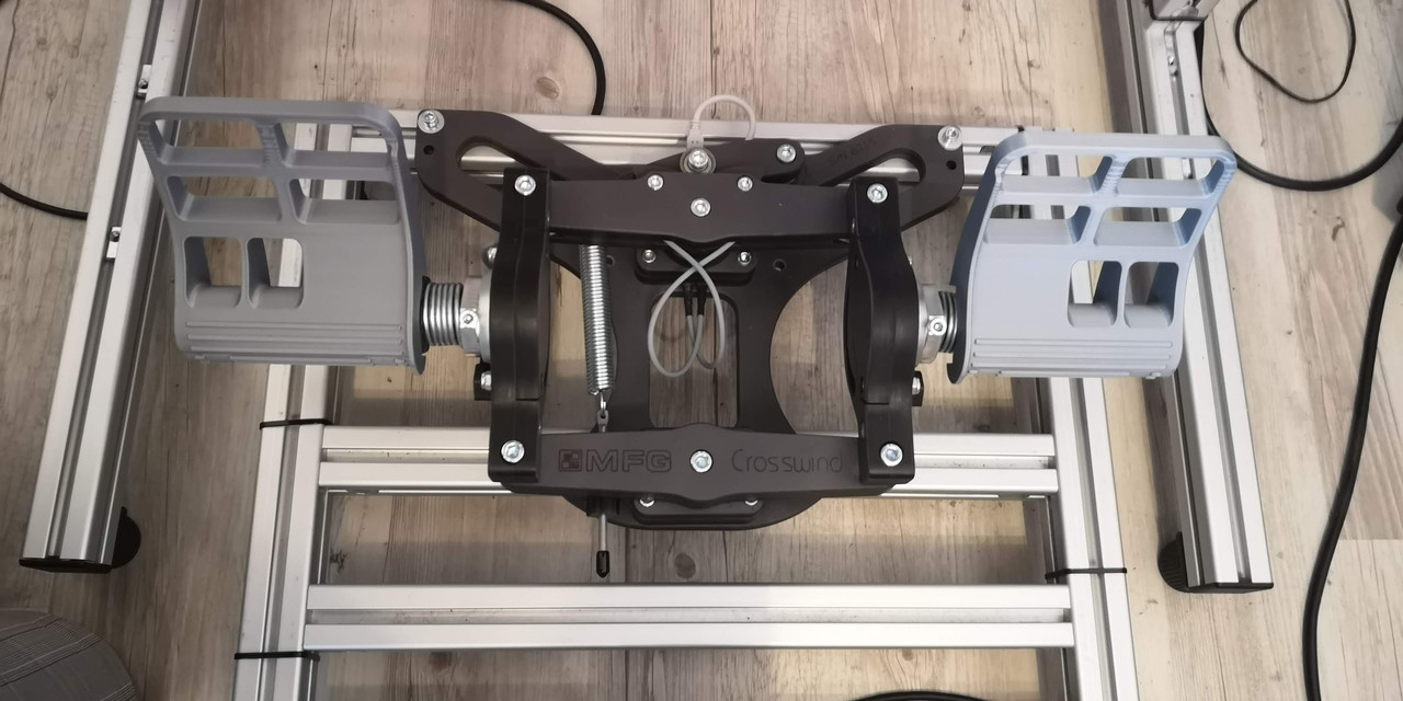
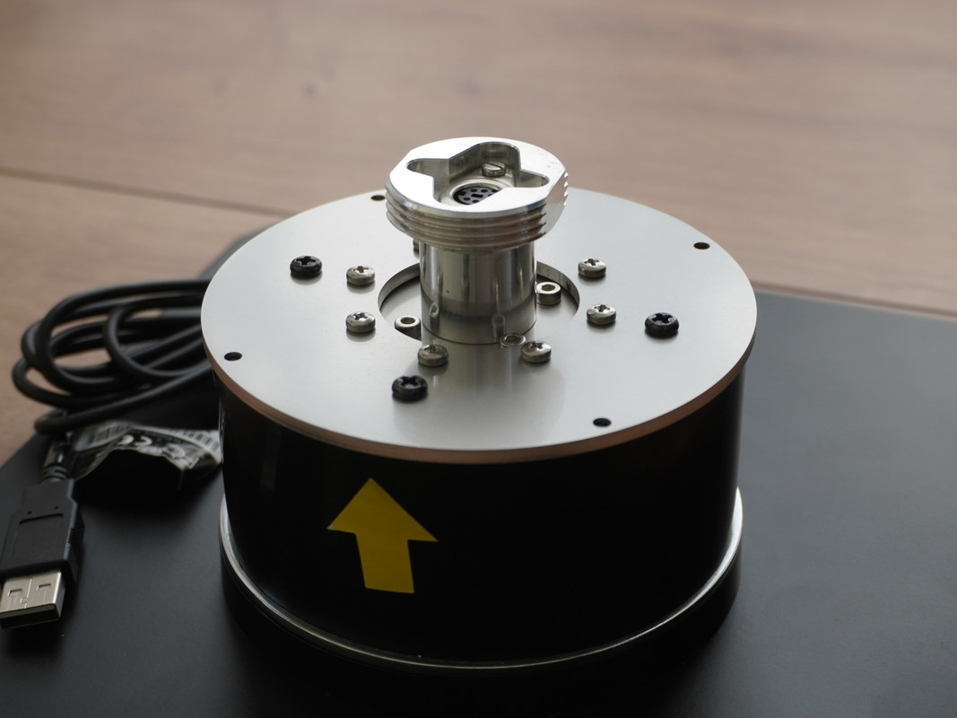
Here are a few pics of the finished FCC R4 with the Warthog mounting plate.
As you can('t really) see the "FCC controller" is doing its job in converting a Warthog base to a force sensing base. I won't show off the FCC controller yet as I am still missing a few LEDs indicating when the axes are centered and a few SMD elements for ADC filtering. Just to clear things up, the FCC controller is a completely optional mainboard that makes the FCC R4 work as standalone unit, eg in a simpit. However, the FCC R4 will also work natively with a Cougar mainboard and mounted in a Cougar base! I will explain all of that in detail in the next update.
On 8/19/2023 at 9:44 AM, HILOK said:you truly are a gifted engineer! great great stuff, thanks for all your commitment !!
since you mentioned the F18 grip, i would like to suggest some ideas:
1) as TM missed to implement the push function in the TRIM switch (which as we learned since the release of the F15 has an important function), maybe you could find a replacement solution to this issue? (maybe connect the trim push switch in parallel to the RECCE?)
2) for a long time i've been thinking how cool it would be, if TM had designed the CASTLE sw and the TRIM sw in such way that they were 'plug & play' interchangeable, so that their grip would also 100% replicate that of the harrier
Thank you so much for the kind words!
1) Since the 3 4021 shift regs in TM sticks support up to 24 buttons but only 23 are used, it should be possible to add 1 more button. I just don't know if TARGET will be able to recognize that. I'll give that a try when time permits. As mentioned above my trim incl. push button will be finished soon, now that the PCBs arrived from the fab.
2) The F-18 TM 5-ways are much larger in diameter than the Cougar/ Warthog hatswitches. The trim will fit into the Castle no issues with an adapter, but the other way around is problematic. But I can simply pop the castle hat to my 5-way trim and it should fit. Overall absolutely solvable I'd say!
On 9/17/2023 at 12:47 PM, Phantom711 said:I find the feel of the switches of the TM F-18 stick rather poor. I can‘t understand why they didn‘t use the same ones as on the Viper stick even though they have the same functionality (i.e. 5-way hat).
Do you consider making replacements for the TM F-18 stick as well? Especially my Weapon Select Switch is rather sticky in the forward position.
Yeah, I dislike them as well! They imitated the tactile OTTO T4 Minis in a needlessly large footprint and used some new cheapo rubber buttons instead of the tried and tested OMRON buttons. Not a fan at all! Does anybody know if the real F-18 stick uses the tactile hatswitches, I know for a fact the F-16 has the standard T4 Minis!
-
6
-
-
Just now, MAXsenna said:
Oh! That's great news. I have three Cougars, that's why I ask.
Smoking? Those that designed the gimbals of the Cougar comes to mind. They obviously tried to correct in the Warthog, but that's not even a gimbal.

True!

-
1
-
-
On 8/17/2023 at 6:41 PM, The LT said:
omg, very interested as my fssb just died on me. This looks very promising
Which FSSB version do you have? I may be able to repair it, just depends if its worth the shipping costs to Germany from where you live.
On 8/17/2023 at 8:09 PM, MAXsenna said:Will the force sensing solution be released for the Warthog base first and then the Cougar?
Cheers!
I planned to do a phased release initially, but since I have taken so long I finished all the models by now. Therefore I can release all models at once (simpit, Cougar, Warthog, FCC standalone controller).
I forgot to mention that I bought a TM F-18 stick for a really good price as it had broken hatswitches. Turns out the problem wasn't broken hatswitches but simply a bad hatswitch design. Initially I reverse engineered the 5-way hatswitches to print a fixed one, but it turned out I can simply cut off a mil from the cheapo rubber buttons in the 5 way and make them actually fit the housing. Took me a while to figure out, but the fix was a small scalpel trim and now I have a perfectly good F-18 stick (and a modeled TM 5-way hat).
I have to say though the F-18 stick has got to be the most overengineered thing I have seen in a while... Whoever designed that thing must have been smoking some mad stuff.
-
1
-
1
-
-
I am actually still very much in business, answer incoming emails regularly and send out orders weekly. I have recently made a large batch of updated mods and even developed new ones. I just don't check the DCS forums regularely anymore. I'll give you guys a quick overview on what I've been up to lately.
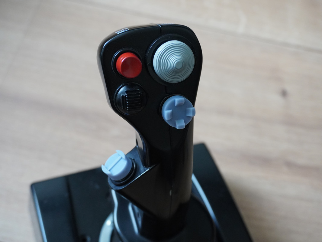
As you may have read earlier in this thread I have designed and made original spec OTTO hats. Now I have adapted these for all the TM sticks, aka Warthog, Cougar and F-22 Pro. Especially the DMS, CMS and radio COM hats should be interesting to a bunch of people.
Furthermore the OTTO T4 replica hatswitches are done and working great! Only the large T4 trim is still awaiting their PCB from the factory, but the CAD files and prints are done. The hatswitches are soldered with a 5 or 6 wire connector depending on 4- or 5-way configuration. The switch itself is the same high quality (9-way) ALPS hat used in eg the Virpil stuff.
I have also designed a CH hat replacement that is easily printable and has the exact same internal geometry and function as the CH hats. It is available in a 4-way and 5-way hat config (aka 4-way + push button). Obviously I can make any hat style compatible to this hatswitch. These hatswitches may be interesting for the DIY community as the original CH hats cost 50$ over at Mouser.
Next, I have completely redesigned the 4021 shift regs and made the latest and greatest rev 2.1. These have the header pin layout adjusted to fit a breadboard and now finally have two mounting holes.
Finally and most importantly, I have finished the Force sensing base and the FCC controller aka Warthog standalone mainboard. I'll be posting pictures of the boards as soon as they arrive from the fab.
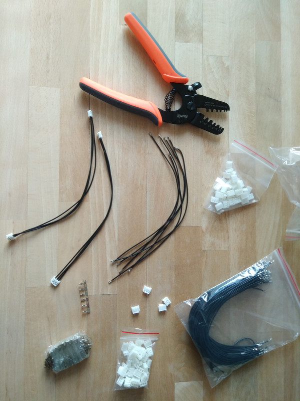
Here I am preparing the cable connectors for the FCC wiring. Sadly I wasn't able to find any premade cables suiting my needs, so I need to crimp them all myself. Oh well...
Sooo, I'd like to share with you some info on my force sensing base and what will set it apart from the rest! While I just sent the latest & hopefully final PCB designs to the fab, I was testing my curent design against the FCC3 as well as the FSSB R3 from Realsimulator. While I like the FCC3 concept better than the FSSB, which has a noisy MCU directly on the (otherwise) analog board itself, the FCC3 PCB (and any of the recent blatant copies for that matter) have some major design flaws which can and should be ironed out.I recently found a well suited opamp for the design which has 4.3x less noise than the FCC3 and still 2.6x less noise than the previous opamp I used, while also having much better CMMR. Just let me reiterate as it's easy to miss the significance, that would be a 430% decrease in noise! Before celebrating I need to test if it really performs to that level, but it surely looks promising.The FCC really lacks a ground plane and that shows on the scope, especially in RFI susceptibility. Therefore I made a well structured layout with a ground plane as basis and also added an optimized RFI filter circuit to restrict signal bandwidth. Then The FCC3 completely ignored supply decoupling, so I got that fixed as well. Obviously the final layout is my little trade secret for now, but you can see the PCB backside is a 100% perfect clean ground plane and no pesky signal traces crossing in all sorts of unfavorable ways.IMO this force sensing base is electrically state of the art now and will leave the other options in the dust!
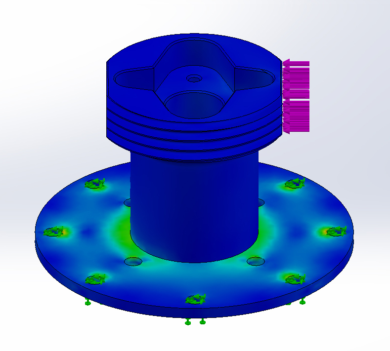
I also ran some FEA simulations to get the perfect mounting spot for the sensors. The positioning on the FCC3 seemed improvable and I also wanted to show the difference an additional pressure plate makes to strain uniformity and why it is worth to add that extra complexity. I know most of the force sensing bases omit this one and I don't understand why, as it makes a big difference! Symmetry in the colored areas (strain) is what we are striving for. Have a look!
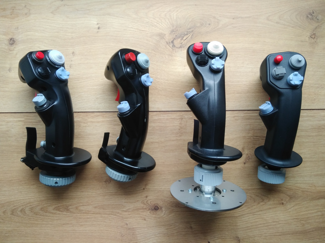
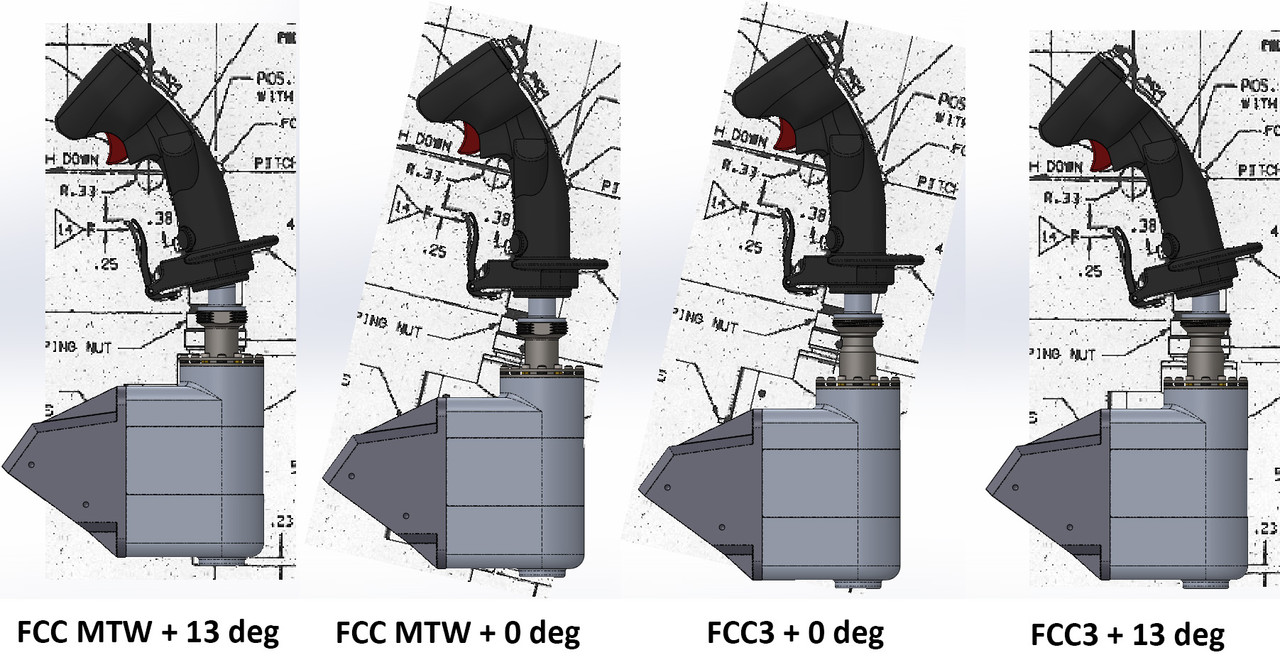
Finally I took a few CAD screenshots to compare the physical dimensions of the FCC3 with my force sensing base and the F-16 blueprints. I tried my best to make it true to the F-16 dimensions and with my 13deg tailpiece it's pretty much spot on. In this picture the grip itself is overlayed to the blueprints and you can see by how much the lower base is off in comparison to the blueprints. Basically the grip mounted on an FCC3 sits a few cm taller than the SSC in the F-16 does.
Hope that wasn't too much rambling for you guys!
-
4
-
4
-
-
On 1/8/2023 at 10:23 AM, tomcat_driver said:
Hello @rel4y, I have a question. I originally upgraded all the sensors on my CH HOTAS and on a later date, the throttle's board but not the stick's. Would it be possible for me to swap the stick and throttle boards so I have the upgraded relay's board in the stick instead?
Yes, that's possible. The upgrade boards are the exact same connector wise and differ only in firmware setup. You would just need to reinstall the original CH board of the Throttle. Contact me via email and I will upload the correct firmware for you. I need to know the mainboard rev (1.0- 1.3) number, it's printed on the PCB front.
-
1
-
-
On 1/5/2023 at 12:13 PM, Cyclontrail said:
@rel4y Hi, do you have any more sensors in stock please? My hotas cougar throttle pot is dead and need a replacement as soon as possible please. Any help with this is very much appreciated. Thanks.
Please email me for ordering, I have everything except the ANT sensors in stock and these will be back in stock in a few days as well!
-
20 hours ago, - Sonic - said:
hi...you still product items?
Yes, still making them. Just send me an email, see first post of this thread.
-
Nice, that's exactly the same solution I came up with. Only I used the expensive switches from Knitter (MPS 103F) and printed the hat part as well. Now I am gonna order a bunch of these from Ali to test. Great work!
-
1
-
-
I have zero experience with the cub hall sensors, but I find it unlikely that the hall sensors themselves are broken. I'd suggest checking the cables i.e. wiggle on them and look for a loose contact or an oxidized connector.
But I'm not sure how the gimbal is constructed. In case the hall axle is part of the gimbal mechanics itself, it's possible that the sensor is mechanically worn out. However, I doubt the Uber gimbal is constructed like that as that would be pretty underwhelming...
-
16 hours ago, pr3sidentspence said:
My stick pots look very different from what you have pictured here; mine are short metal cylinders. Will your replacements work for me? Is there a mounting adapter? AmI just really confused?
That's an Uber gimbal that already comes with (cub?) hall sensors.
-
1
-
-
Just realized, I haven't posted anything in a while. Now that the days are getting shorter and rainy, a lot more work tends do get done in the hobbyshop!
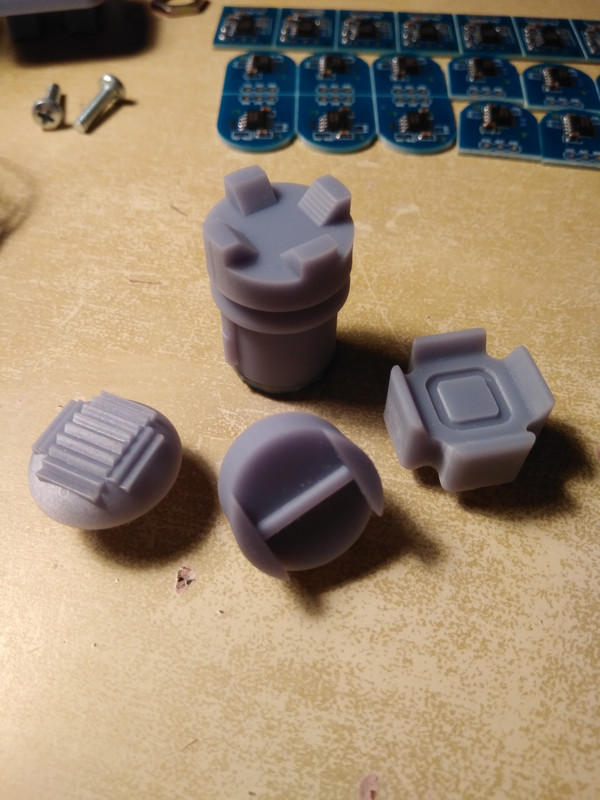
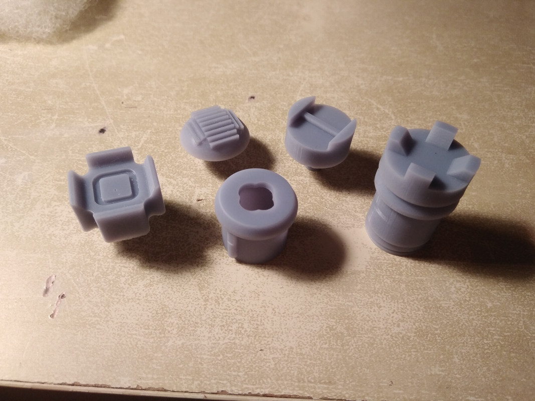
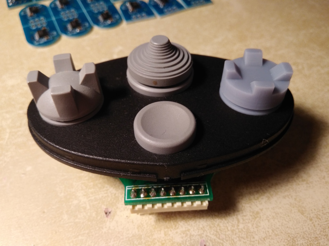
If you guys remember the OTTO hatswitches I posted about a few months ago, here are some printed ones. The CMS hat is now also exactly modeled after an original F-16 one. The prints are not perfect as I forgot to remove all the bubbles in the resin, but they still look pretty good imo. Case dimensions and travel (10 deg) are exactly to OTTO spec, but they are modeled after the tactile ones (OTTO T4T). So they are clicky and not springy. The big trim can be springy or clicky, but I haven't printed one yet.
I'll start to show off a lot more stuff and also get back to the force sensing base. I supplied a bunch of modified force sensors to commercial customers but I need to make it finally available to retail...
-
4
-
1
-
-
6 hours ago, Icaro_07 said:
Sorry, I don't own a throttle quadrant. If I remember correctly the pots were soldered to a PCB in the within the quadrant.
-
8 hours ago, Machinegun417 said:
Can you tell me where the wires go. Thanks
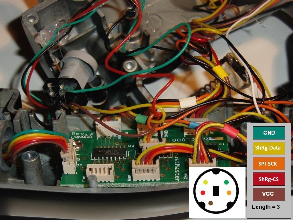
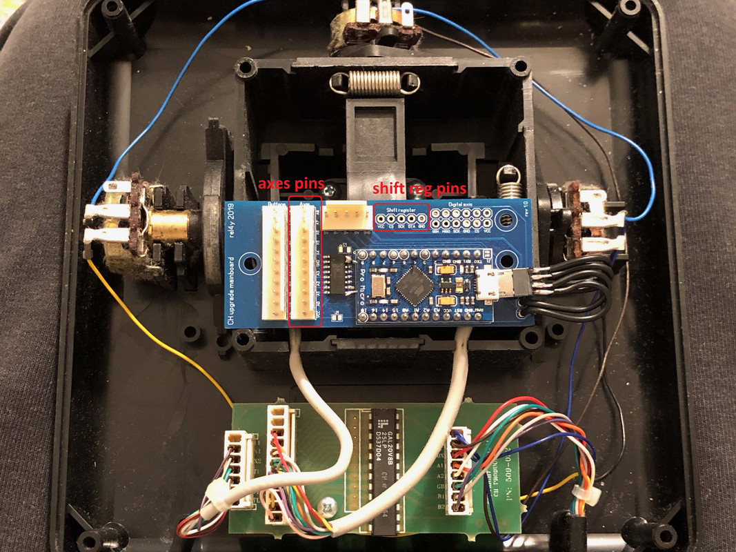
Absolutely! The five signal wires of the stick go to the shift register bay of the upgrade mainboard. I will attach a picture which wire is what (the Cougar has the same color coding as the F-22 Pro afaik).
The following two pictures show the shift reg bay and the axes bay on the mainboard. The shift reg pins are labled with VCC, CS, SCK, DTA & GND (from left to right). DTA = data on the Cougar SR picture. Now it should be easy to follow the color coding and connect the pins correctly.
The two axes pots are connected in the following way, the two middle wires (green & gray) of the pots are connected to axis 1 and 2 pins. These are the signal output. Of the outer wires one must each be connected to the VCC and GND pin on the axes bay. Which way round doesn't really matter as pots have no polarity, it only results in the axes having its zero and max output reversed. But you can always adjust that to your liking afterwards in software.Please only connect them to the VCC and GND pins of the axes bay, as this is the "analog" side of the board and will result in the most accurate voltage readings of the ADC.-
1
-
-
Veeery nice! Good job, both of you!
-
8 hours ago, csdigitaldesign said:
I have heard nothing back from him since sending him images of the issue. It's been days. He responded in the beginning right away. Not sure why he's not responding. I won't assume he's ignoring me yet.. too soon for that. It definitely does not fit. Here are the images I sent rel4y. You can see the posts below the senor in the first image but they are mirrored on the other side of the clamshell casing. You can see what I mean in the top of the second image. If you look you can see the blue diode thingy on the left side of the sensor sticking out far too much to clear the post. If you flip it 180 the two posts on the other side have the same issue there is not enough room between them. You can angle the entire sensor 30-45 degrees or so so that it misses the post but then it does not calibrate correctly.
Thats weird. Ive answered your all emails within hours, please check your spam folder. The email attached below was sent on 4/6/22 14:45 CET. Ive told you in my first as well as my second answer you need to rotate the sensor by 180 degrees. You also need to bend the cables out of the way, from the pictures I can tell the post has squashed the cables. Best to stick the post through with one cable on the first side and two on the other. It definitely fits and your sensor isnt different than all the others I have sent out. You can temporarily install it in a footbrake to see that it not only technically works, but also in practice.
If for some reason your mould is different than mine, then maybe take a file and file off half a mm of the inside of both posts so the blue trimmer fits in between. Its hard to diagnose whats going wrong from afar.
I am sorry that you are having trouble installing it. If you really think you cant make it fit, then send it back to me and I will refund you.
SpoilerIt fit mine as well as around 20 other peoples CH Pro pedals, so Id be suprised if it didnt fit yours. The blue thing is a precision trim pot and needs to bent upwards slightly, then it will not interfere with either the bottom recess nor the distancing poles. If you bent it slightly it will fit in between the two posts on the other side as shown in your picture! You need to rotate in 180 degrees.Did you see the message from the user samtheeagle in the forums?Kind regards,Marvin-
1
-
-
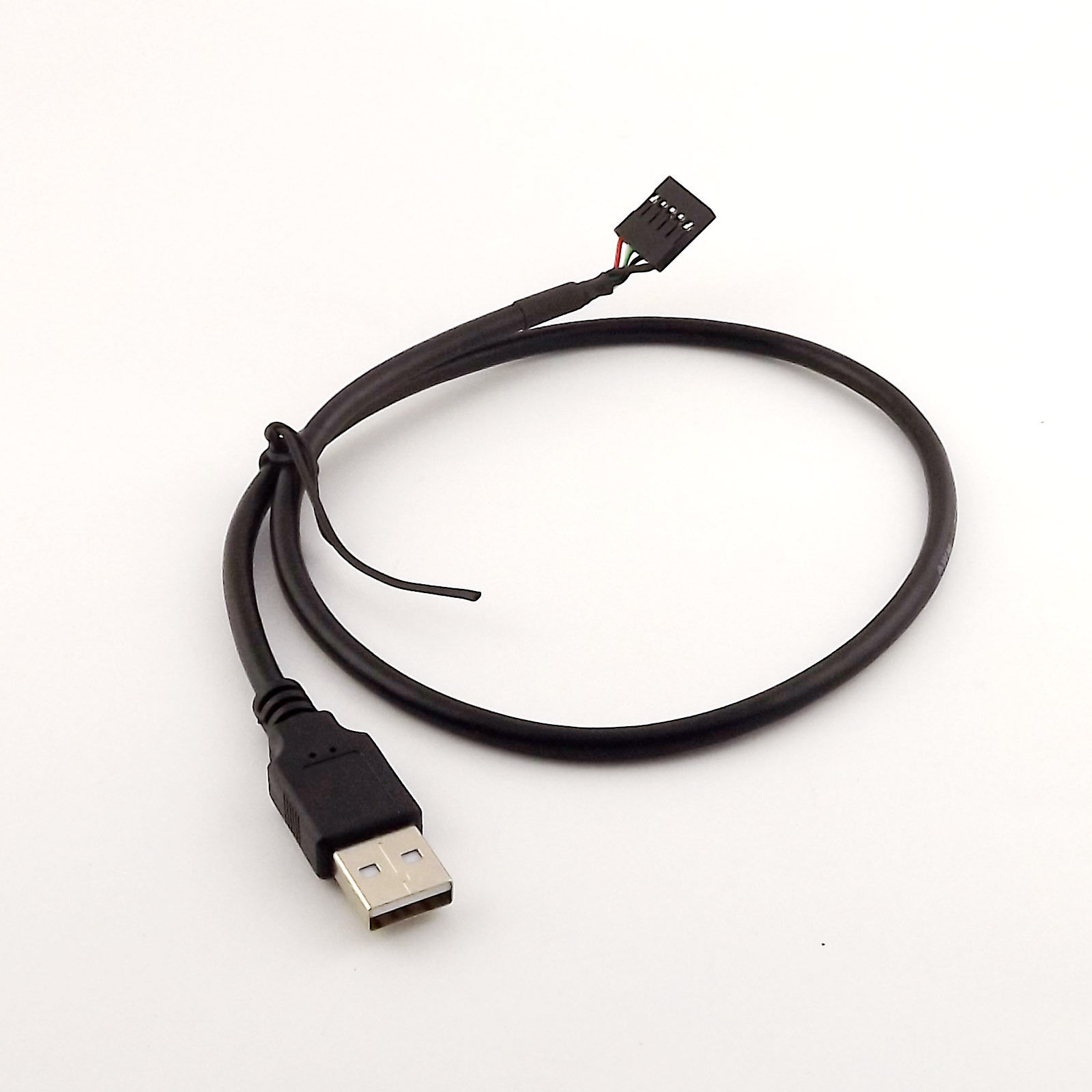
There is either left of the shift register pins (red box) a 0.1 in spaced 5P USB connector (says USB above it) or you can unplug the Micro USB and use it like the Cougar Throttle adapter with a Micro USB cable. Both are working the same and you can use whatever is more convenient. For my personal F-22 I bought a 5pin header to USB A cable and attached it to the USB pins. Below is a picture attached, but mine is a bit longer like 2m. You can look for "USB A to 5 pin dupont" eg.
PS: I found the F-22 shift reg pinout/ wire color. It seems to be the same as the Cougars.
green - GND
yellow - DTA
orange - SCK
red - CS
brown - VCC -
6 hours ago, Machinegun417 said:
Does anyone have the instructions for the F22 Pro USB 12 Bit resolution Mainboard??
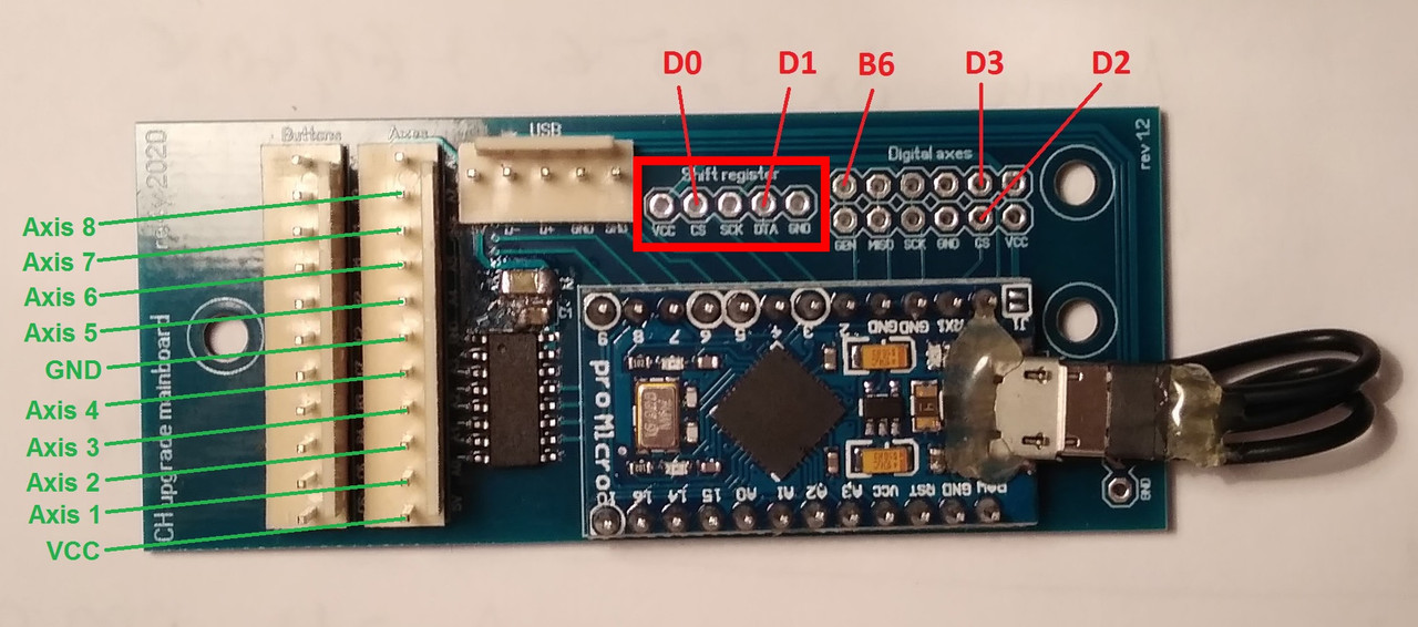
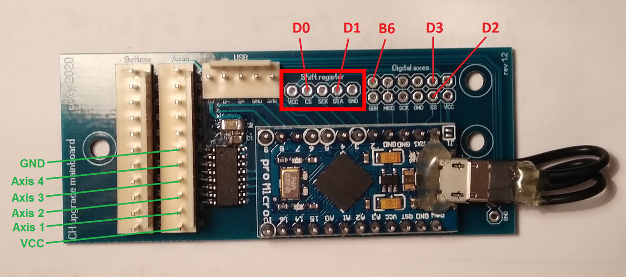
Here is a picture of the axis layout of the mainboard (green text). Btw, the unlabled pins above the green ones are four more 12 Bit axes. Please ignore the pinout of the expansion bay (red text). The buttons of the grip itself are wired to a TM typical 4021 shift register and only five wires lead out of the grip. I dont know the wire code by heart, but will have a look. These five wires (VCC, GND, SCK, DATA, CS) need to be connected to the shift register inputs (red box).
-
6 hours ago, ApacheLongbow said:
Hi rel4y, do you have any CH Pro Throttle mainboard upgrade available?
Cheers
Yes, in fact I do! Feel free to contact me via email.
-
1
-
-
Do you ever sleep?

-
Aww man, Im sorry! Some days are just worth erasing from memory...

-
9 hours ago, GunslingerII said:
Got it , no bypass needed. thanks for that
So , I assume the colored pin connections order makes no difference also?
There is a specific order of the six pin cable, but it depends on the version of the USB standalone adapter. I changed the layout on rev 1.3 to an easier all in line config. You can send me an email with your adapter revision and I will send you the corresponding PDF with instructions.
-
On 3/18/2022 at 5:40 AM, Smile2137 said:
I have an F-16 grip and a replacement trigger,I can try to help you if needed.
Man, that would be awesome! Ill send out a PM in a minute!
6 hours ago, Milker said:Well... first, thank you all for making Cougar a state of the art HOTAS!
Bought mine in 2006 and never used it since now (2022)! Brand new and i also have Ant elevation knob with lack of center detent and little spikes.
Opened, cleaned it and it is a little bit better... It´s hard to find the right Pot to it... think i will go straight to HALL sensors, just mailed Rel4y.
You guys helped me getting it to work in Win 10 so thank you very, very, very much.
Greetings from Portugal,
Milker
Ill answer your email also in a minute!
23 hours ago, GunslingerII said:Guys, I have a question on the REL4Y's USB board in my 3.8v TQS BOARD, and whether the six pin connectors must be connected in a specfic
order? Also can I do the jumper wire to bypass the 3.8 resistor as shown in a Miles post.I am a total circuitry dunce.
GunslingerII
The trhottle mainboard version doesnt matter for the USB standalone adapter, as it has its own voltage regulator. So dont worry about doing any bypass mod.
-
1
-
-
I am getting along nicely on a quest to a complete & up to spec F-16 HOTAS.
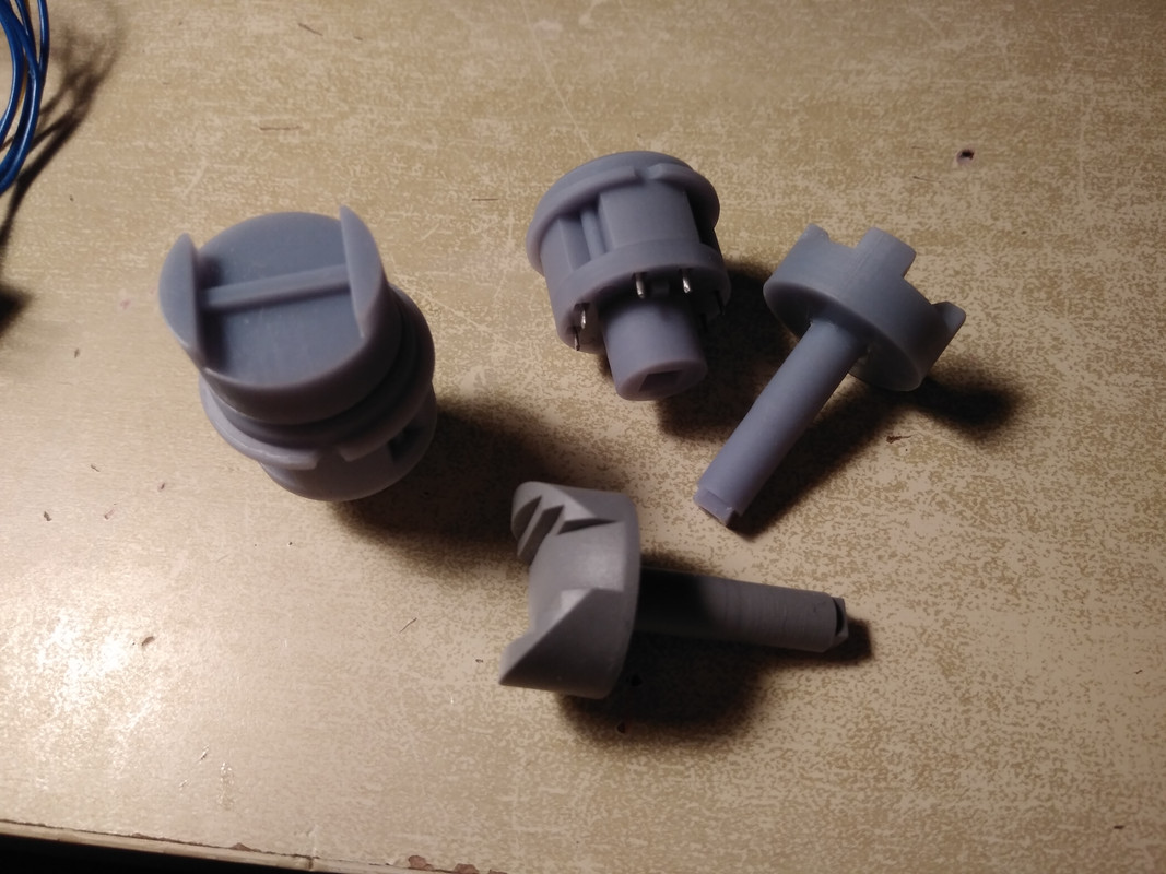
While there wasnt much time this week for CAD models, I have gotten pretty far along on the paddle switch. Yes, I know there is already a STEP file of the paddle around, but first of all I dont own the rights to use it and second I will get it more accurate to the original part.
Then, finally, I printed a calibration jig for the Cougar stick sensors so I dont have to mount every single sensor in the Cougar base for calibration. Thats quite a few years late, but better late than never!
There is also another batch of Cougar stick sensors in the works and I am in the midst of assembling them currently. With the MSLA printer I will also be able to finally complete the MAN RNG sensor for the Cougar and also build an improved ANT v2 sensor in the future. The technology allows for much more precise prints than what was possible with the SLS printed Polyamide parts.
Furthermore, I can now offer analog MagREZ sensors based on the standard 34,4mm M3 hole spacing as well as digital TLE5011 ones. The only thing missing for these is a nice SMD stencil to make production easier, as currently the only option is hand soldering...
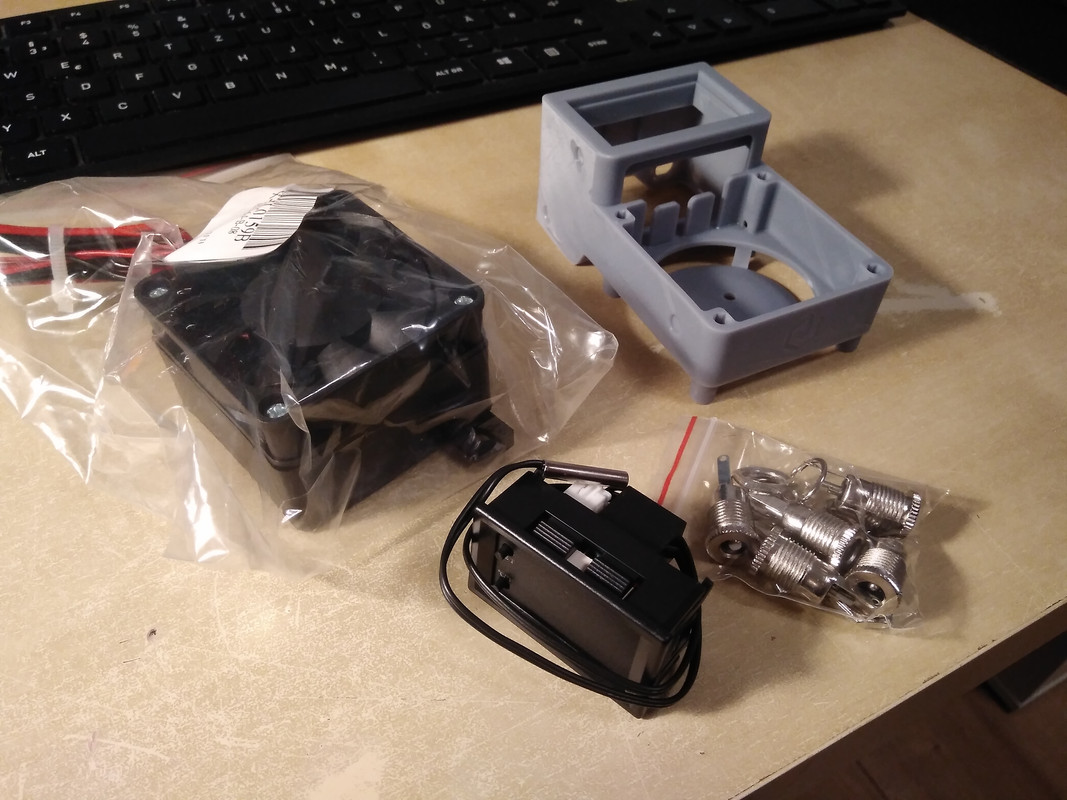
Lastly, I made a nice PTC heater unit to be able to print on my resin printer even in cold temperatures. The case is also MSLA 3D printed and its a project from thingiverse. It turned out well, so I thought I would show off some pics.
-
4
-


TM Cougar & CH magnetoresistive/ hall sensor kits
in Thrustmaster
Posted · Edited by rel4y
Yes, in my wall of text, it probably wasn't clear. I had to write in a hurry to at least get out the good news, since I left for vacation yesterday. However, I'll answer all you guys nice mails and PM's today! Thank you so much!
My FCC version has different V/force output than the FCC3, that's why I said the preset sensitivity settings of uri_bas software won't be accurate. Since I can adjust amplification and also measure force input, it was easy to set up a custom sensitivity for me. On my prototype unit I even have hardware set pitch on a different amplification than roll, but that's just me playing around. As I wrote above, initially I placed the sensors so I could get full force output at 40lbsf, but that was tendinitis inducing and I quickly scrapped it.
I ran into two minor problems though, my FCC R4 rev 1.3 has rail to rail output, so pretty much 0.1-4.9V. I wasn't able to make use of the full range except with the MMJoy2 config, now I understand why. The rev 1.2 worked fine though.
How do I set the Warthog mode?
Second was stair stepping at quick input release. Just to be clear, there is no jittering whatsoever, the filtering works and output is silky smooth. I see stair stepping at small time differentials during force reversal. Open eg VKB joystick viewer and in quick succession go pitch up and immediately release input. After the top you will see a stair step before returning to a smooth curve. When reading raw output signals (unfiltered from the ADC) of the FCC R4 I don't see these stair steps, so my guess is the software is running into some averaging issues.
And again, I am absolutely impressed with your software and these really are minor issues! Maybe, if you find the time and are interested, we can work together on looking into the issues? You can PM me if you are interested in testing one in person.
Thank you so much, guys!